Background
So by way of background, I know this is not a unique post on the workflow to produce 3D prints from images. However, I hope it gives some guidance specifically for taking images and converting them into stencils for use in glass work.
The conventional way of achieving this involves cutting shapes out of Mylar sheets. These stencils are used to hold glass frit, which is then fired. For complex shapes with narrow sections, Mylar is a little too thin and flexes too much when taken off.
This method attempts to limit this by 3D printing a slightly thicker stencil. The balance here is between having enough thickness to keep the template rigid and not being so thick that the frit sags when the stencil is removed.
Work flow
To get an STL file that can be printed, I use Inkscape and OpenSCAD. Inkscape converts the image to a scalable vector format that can be cut out of a square of plastic in OpenSCAD.
Converting an image to a vector based format
I convert images to a vector based format to get a smooth edged graphic. You can miss this stage out and take a PNG straight into OpenSCAD using surface however as most images are JPEG format there will be noise artifacts and the edge is very jagged as each of the pixels in the original image are visible.
I will start with a simple noisy JPEG image:

If we open this in Inkscape we will be asked to determine how to convert. I optimise for smoothness as this is a quick process with these types of graphics:

Once the image is imported, we can convert it paths using the Trace Bitmap … option on the Path menu. The options on this dialog are key – feel free to play with the values but my recommendations for black and white images are:

In the Mode tab I use Brightness cutoff; the key changes are on the Options tab:
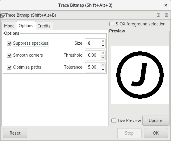
Here I set the Smooth corners threshold to 0.00 (the minimum) because I want sharp corners and the Optimise paths to 5.00 (the maximum) to reduce the number of segments in the arcs.
At this point, I save the resulting file as a DXF file (Desktop Cutting Plotter). Note, whilst there are a number of warnings about using this format with OpenSCAD, I have not met any problems importing this (yet!).
Using the DXF file to make a stencil
The stencil can now be put together in OpenSCAD. Typically, the shape will be cut out of a cube. The difficult bits are getting the graphic to be a sensible size and putting it in the centre of the cube.
Typically these stencils are to create designs that can fit on 10 cm tiles, which means I am looking at stencils in the 5-8 cm range. For this example which is round I have chosen 6 cm as the size. The frame around it is visual guess work – in this case 7.5 cm looked about right.
1 mm thick stencils give the right balance of stiffness and depth of frit glass when the stencil is printed in PLA plastic.
Putting this all together, if the exported DXF file is in samplegraphic_ink.dxf, the code to build the stencil is:
difference() {
cube([75,75,1]);
resize([60,0,2], auto=[true, true, false])
    linear_extrude(height=10)
    import("samplegraphic_ink.dxf");
}
The resize function that allows us to maintain the scale of the piece given one dimension makes this easier to achieve. I set the height of the stencil to cut out to 2mm because I have occasionally had artifacts in the STL file when it is exactly the same height as the cube it is cut out of.
When it is rendered it looks like this and at this point it can be exported to STL:

That’s all there is to it. Enjoy.
